The Future of Healthcare: AI, Wearable Technology, and the Role of ASICs
While healthcare may have lagged behind sectors like fintech or education, its digital transformation in recent years has been nothing short of seismic. New technologies as well as social and environmental challenges have propelled the industry forward, from the emergence of telehealth and virtual appointments, to machine learning (ML) powered diagnostics and remote patient monitoring. One major technological development that is particularly suited to healthcare is wearable technology. The market for wearable devices has boomed in recent years, with some analysts predicting it will grow by 97% to reach $161 billion by 2033. Much of that growth can be attributed to applications in healthcare, whether it’s individuals looking to take control of their own health, or healthcare providers looking to improve their diagnostic and monitoring capabilities.
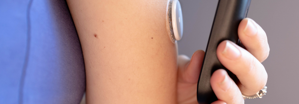
Wearable devices are nothing short of game changing. Equipped with advanced sensors, they can continuously monitor vital signs such as heart rate, blood pressure, glucose levels, and more, providing invaluable real-time data to patients and healthcare providers without the need for cumbersome home kits or frequent hospital visits. When combined with AI and ML, wearable devices have the potential not only to improve patient outcomes, but drive the industry forward in terms of clinical research and diagnostics. From cochlear implants and hearing aids, to remote fertility monitoring and mobile cardiac telemetry, the possibilities are seemingly endless.

However, there is a catch. Wearable devices are small and inconspicuous by design, and are expected to function continuously for long periods of time, and that creates engineering problems. Battery power and heat dissipation and two areas that must be carefully considered, and with an increasing number of devices expected to perform at the edge, local processing capabilities are also a factor.
Enter ASICs, or Application Specific Integrated Circuits. These specialized chips are designed to perform dedicated functions with higher efficiency and lower power consumption than general-purpose processors. In the context of healthcare, ASICs are crucial to ensuring that wearables can operate for extended periods on minimal battery power, making them reliable for continuous monitoring. ASICs can also facilitate edge computing, where data processing occurs directly on the device, preserving privacy and ensuring functionality even in areas with poor connectivity. Before we explore the technology in more detail, let’s first explore the reasons behind the boom in wearable technology and how it’s creating unprecedented opportunities for early detection, continuous monitoring, and personalized treatment plans.
The burden of non-communicable diseases (NCDs)
Non-communicable diseases (NCDs), including cardiovascular diseases, cancer, respiratory diseases, and diabetes, are the leading cause of death globally, accounting for three out of four deaths worldwide, according to the World Health Organization (WHO). These chronic conditions place a tremendous burden on healthcare systems and economies, particularly in low- and middle-income countries, where healthcare resources are often limited and overstretched. Early detection and continuous monitoring are essential strategies in combating NCDs, as timely intervention can prevent severe complications, remove some of the burden placed on healthcare delivery, and ultimately reduce mortality rates.
Traditional methods of diagnosing and monitoring NCDs have typically relied on sporadic testing of key indicators such as blood pressure, glucose, and cholesterol levels. However, this approach can actually hinder early detection and timely intervention, as critical changes in a patient’s condition may go unnoticed between tests. The advent of wearable technology addresses this gap by providing continuous, real-time monitoring of vital signs. These devices, ranging from smartwatches to specialized medical monitors, collect data seamlessly and frequently, offering a comprehensive view of a patient’s health status. By enabling ongoing assessment and immediate alerts to potential health issues, wearables empower both patients and healthcare providers to take proactive measures in managing NCDs effectively.
The synergy of wearables, AI, and edge computing
Remote patient monitoring isn’t new. What is new, however, is the rapid design and manufacture of new devices that can leverage AI and ML to maximize its potential. AI excels in processing and analyzing vast amounts of data, identifying patterns and anomalies that might be missed by human observation. In healthcare, AI-driven analysis can enhance the accuracy of diagnostics and prognostics, offering personalized insights based on an individual’s unique health data, and predicting health issues before they become critical.

One essential piece to this puzzle is the concept of edge computing. Traditionally, data from wearables would be transmitted to cloud servers for processing, requiring significant bandwidth and posing potential privacy risks. Edge computing avoids these issues by processing data locally on the device itself. This approach not only reduces the amount of data that needs to be transferred, but also ensures that sensitive medical information remains secure. What’s more, edge computing enables devices to function effectively even in areas with poor internet connectivity, a crucial advantage in low- and middle-income regions where NCDs are most prevalent. By embedding AI capabilities directly into wearables through advanced chips like ASICs, healthcare technology can provide faster, more reliable, and more secure solutions, revolutionizing the management and treatment of chronic diseases.
Power efficiency and the role of ASICs
The design and manufacture of wearable tech is not without its challenges. Wearables are often required to operate continuously for extended periods, sometimes 24/7, to provide real-time health monitoring. Ensuring that these devices consume minimal power while maintaining high functionality is crucial not only for user convenience but also for the feasibility of continuous health monitoring. ASICs are custom-designed chips tailored to perform specific tasks with greater efficiency than general-purpose processors. Unlike traditional processors, which may carry unnecessary functionalities that drain battery life, ASICs include only the circuits required for the specific application, thereby reducing energy consumption. This optimization allows wearable devices to function longer on a single battery charge – critical for uninterrupted monitoring.
ASICs can also facilitate the integration of multiple functions onto a single chip, including analogue front-ends (AFEs), data converters, voltage references, and oscillators. This integration not only reduces the physical size of the device but also minimizes overall power consumption by eliminating the need for multiple discrete components. Local data processing is also possible, reducing the need to transfer large amounts of data to external servers. This local processing capability allows for real-time analysis and decision-making, essential in healthcare settings where timely responses can be life-saving. Although developing an ASIC involves higher upfront costs compared to using commercial off-the-shelf (COTS) components, the long-term benefits often outweigh these initial investments. For instance, integrating multiple functionalities into a single chip can significantly reduce the bill of materials (BoM) and streamline the supply chain, leading to cost savings over time. Put simply, ASICs will continue to play a crucial role in enhancing the power efficiency and functionality of healthcare wearable devices, paving the way for more effective and accessible health monitoring solutions.
As healthcare technology continues to evolve, the fusion of AI, wearable devices, and ASICs heralds a new era of proactive and personalized medicine. By overcoming the challenges of power efficiency and data privacy, these innovations promise not only to enhance patient care but also to democratize access to advanced medical diagnostics and monitoring, particularly in underserved regions.
by David Rivas -Marchena