EnSilica: Leading the Way in FinFET Technology
In the dynamic landscape of wireless communication, semiconductor innovations play a pivotal role. Among these, FinFET technology stands out as a game-changer. Let’s explore how FinFETs are shaping the future of 5G and satellite communication.
MIMO Systems: A Brief Overview
Deployment of 5G terrestrial and satellite communications relies heavily on the integration of Multiple-Input, Multiple-Output (MIMO) systems to meet the link budget requirements and mitigate interference.
Fin field-effect transistors (FinFETs), represent a departure from traditional planar transistors. Their three-dimensional fin-like structure allows for better control over current flow, reducing the leakage and improving power efficiency. This technology has been the key enabler for the design of highly integrated digital radio ASICs, based on RF ADCs and DACs, supporting multiple standards.
Key Changes with FinFETs
- Improved RF and Analog performance:
- FinFETs exhibit superior Gm and Rout characteristic, which is paramount to implement the highly linear analog signal processing required in MIMO systems.
- Excellent RF performance with fT values of 600GHz.
- MIMO signals remain pristine even in challenging environments.
- Power Efficiency Boost:
- The subthreshold slope of FinFET devices is practically ideal. This drastically reduces leakage current—the silent power drain—that has plagued semiconductor devices for years.
- For 5G devices and satellite communication terminals, where power constraints are stringent, FinFET-based designs shine.

Design Challenges
Despite the improvements in performance, FinFET technology introduces complexity in the design that impact the work of engineers and their approach to RF ASICs.
Now more than ever analog designers, who delve into the intricacies of FinFET, need accurate modelling to ensure that their designs align with the theoretical predictions. Rigorous simulations validate performance metrics, allowing for confident deployment.
At the same time designers face a delicate balancing act. Performance, power consumption, and chip area—these factors intertwine. Effective trade-offs lead to optimized designs that meet real-world requirements.
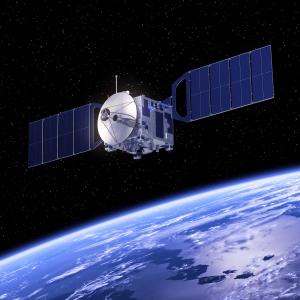
Impact on Satellite Communication
- Custom ASICs empower cost-effective, low-power satellite broadband user terminals.
- These terminals, based on MIMO communication systems, enable seamless connectivity, even in remote areas. Collaborations with space agencies underscore the commitment to advancing satellite communication technology.
- Hybrid satellite/5G networks are on the horizon, promising ubiquitous connectivity.
The journey through the FinFET landscape is one of innovation, precision, and impact. As we embrace the future of wireless communication, semiconductor advancements remain a beacon—a testament to human ingenuity.
For more in-depth insights, please refer to the full article in the Microwave Journal by EnSilica’s FinFET expert Gabriele Devita